Pressure, friction and flow

Pressure, friction and flow are three important
characteristics of a pump system. Pressure is the driving force responsible for
the movement of the fluid. Friction is the force that slows down fluid
particles. Flow rate is the amount of volume that is displaced per unit time.
In the metric system, flow is in liters per second (L/s) or meters cube per
hour (m3/h).
Pressure is often expressed in pounds per square
inch (psi) in the Imperial system and kiloPascals (kPa) in the metric system.
In the Imperial system of measurement, the unit psig or pounds per square inch
gauge is used, it means that the pressure measurement is relative to the local
atmospheric pressure, so that 5 psig is 5 psi above the local atmospheric
pressure. In the metric system, the kPa unit scale is a scale of absolute
pressure measurement and there is no kPag, but many people use the kPa as a
relative measurement to the local atmosphere and don't bother to specify this.
This is not a fault of the metric system but the way people use it. The term
pressure loss or pressure drop is often used, this refers to the decrease in
pressure in the system due to friction. In a pipe or tube that is at the same
level, your garden hose for example, the pressure is high at the tap and zero
at the hose outlet, this decrease in pressure is due to friction and is the
pressure loss.

Pressure provides the driving force to overcome
friction and elevation difference. It's responsible for driving the fluid
through the system, the pump provides the pressure. Pressure is increased when
fluid particles are forced closer together. A good example is a syringe, as you
push down on the plunger the pressure increases, and the harder you have to
push. There is enough friction as the fluid moves through the needle to produce
a great deal of pressure in the body of the syringe

If we apply this idea to the pump system of,
even though the discharge pipe end is open, it is possible to have pressure at
the pump discharge because there is sufficient friction in the system and
elevation difference.
Friction is always present, even in fluids, it
is the force that resists the movement of objects.

When you move a solid on a hard surface, there
is friction between the object and the surface. If you put wheels on it, there
will be less friction. In the case of moving fluids such as water, there is
even less friction but it can become significant for long pipes. Friction can
also be high for short pipes which have a high flow rate and small diameter as
in the syringe example.
In fluids, friction occurs between fluid layers
that are traveling at different velocities within the pipe. There is a natural
tendency for the fluid velocity to be higher in the center of the pipe than
near the wall of the pipe. Friction will also be high for viscous fluids and
fluids with suspended particles.

Another cause of friction is the interaction of
the fluid with the pipe wall, the rougher the pipe, the higher the friction.
Friction depends on:
- average velocity of the fluid within the
pipe
-
viscosity
- pipe surface roughness
An increase in any one of these parameters will
increase friction.
The amount of energy required to overcome the
total friction energy within the system has to be supplied by the pump if you
want to achieve the required flow rate. In household systems, friction can be a
greater proportion of the pump energy output, maybe up to 50% of the total
because small pipes produce higher friction than larger pipes for the same
average fluid velocity in the pipe
What is friction in a pump system
Another cause of friction is all the fittings
(elbows, tees, y's, etc) required to get the fluid from point A to B. Each
one has a particular effect on the fluid streamlines. For example in the case
of the elbow, the fluid particles that are closest to the tight inner radius
of the elbow lift off from the pipe surface forming small vortices that
consume energy. This energy loss is small for one elbow but if you have
several elbows and other fittings the total can become significant. Generally
speaking they rarely represent more then 30% of the total friction due to the
overall pipe length.

Energy and head in pump
systems
Energy and head are two
terms that are often used in pump systems. We use energy to describe the
movement of liquids in pump systems because it is easier than any other method.
There are four forms of energy in pump systems: pressure, elevation, friction
and velocity.
Pressure is produced at
the bottom of the reservoir because the liquid fills up the container
completely and its weight produces a force that is distributed over a surface
which is pressure. This type of pressure is called static pressure. Pressure
energy is the energy that builds up when liquid or gas particles are moved
slightly closer to each other and as a result they push outwards in their
environment
Elevation energy is the
energy that is available to a liquid when it is at a certain height. If you let
it discharge it can drive something useful like a turbine producing
electricity.
Friction energy is the energy that is lost to the environment due to the movement of the liquid through pipes and fittings in the system.
Velocity energy is the
energy that moving objects have. When a baseball is thrown by a pitcher he
gives it velocity energy also called kinetic energy. When water comes out of a
garden hose, it has velocity energy.
|

I know you are thinking
this doesn’t make sense, how can feet represent energy?
If I attach a tube to
the discharge side of a pump, the liquid will rise in the tube to a height that
exactly balances the pressure at the pump discharge. Part of the height of
liquid in the tube is due to the elevation height required (elevation head) and
the other is the friction head and as you can see both are expressed in feet
and this is how you can measure them.


Static head
Webster’s dictionary
definition of head is: “a body of water kept in reserve at a height”.
It is expressed in terms
of feet in the Imperial system and meters in the metric system. Because of its
height and weight the fluid produces pressure at the low point. The higher the
reservoir, the higher the pressure.

The amount of pressure at the bottom of a reservoir is independent of
its shape, for the same liquid level, the pressure at the bottom will be the
same. This is important since in complex piping systems it will always be
possible to know the pressure at the bottom if we know the height.

When a pump is used to
displace a liquid to a higher level it is usually located at the low point or
close to it. The head of the reservoir which is called static head will produce
pressure on the pump that will have to be overcome once the pump is started.
To distinguish between
the pressure energy produced by the discharge tank and suction tank, the head
on the discharge side is called the discharge static head and on the suction
side the suction static head.

Usually the liquid is
displaced from a suction tank to a discharge tank. The suction tank fluid
provides pressure energy to the pump suction which helps the pump. We want to
know how much pressure energy the pump itself must supply so therefore we
subtract the pressure energy provided by the suction head. The static head is
then the difference in height of the discharge tank fluid surface minus the
suction tank fluid surface. Static head is sometimes called total static head
to indicate that the pressure energy available on both sides of the pump has
been considered.
Since there is a difference
in height between the suction and discharge flanges or connections of a pump by
convention it was agreed that the static head would be measured with respect to
the suction flange elevation

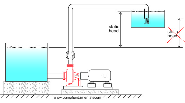
If the discharge pipe
end is open to atmosphere then the static head is measured with respect to the
pipe end.

Sometimes the discharge
pipe end is submerged, then the static head will be the difference in elevation
between the discharge tank fluid surface and the suction tank fluid surface.
Since the fluid in the system is a continuous medium and all fluid particles
are connected via pressure, the fluid particles that are located at the surface
of the discharge tank will contribute to the pressure built up at the pump
discharge. Therefore the discharge surface elevation is the height that must be
considered for static head. Avoid the mistake of using the discharge pipe end
as the elevation for calculating static head if the pipe end is submerged.
Note: if the discharge
pipe end is submerged, then a check valve on the pump discharge is required to
avoid backflow when the pump is stopped.
The static head can be
changed by raising the surface of the discharge tank (assuming the pipe end is
submerged) or suction tank or both. All of these changes will influence the
flow rate.
To correctly determine
the static head follow the liquid particles from start to finish, the start is
almost always at the liquid surface of the suction tank, this is called the
inlet elevation. The end will occur where you encounter an environment with a
fixed pressure such as the open atmosphere, this point is the discharge
elevation end or outlet elevation. The difference between the two elevations is
the static head. The static head can be negative because the outlet elevation
can be lower than the inlet elevation.
For identical systems,
the flow rate will vary with the static head. If the pipe end elevation is
high, the flow rate will be low .Compare this to a cyclist on a hill with a
slight upward slope, his velocity will be moderate and correspond to the amount
of energy he can supply to overcome the friction of the wheels on the road and
the change in elevation.

If the liquid surface of the suction tank is at the same elevation as
the discharge end of the pipe then the static head will be zero and the flow
rate will be limited by the friction in the system. This is equivalent to a
cyclist on a flat road, his velocity depends on the amount of friction between
the wheels and the road and the air resistance

When the discharge pipe
end is raised vertically until the flow stops, the pump cannot raise the fluid
higher than this point and the discharge pressure is at its maximum. Similarly
the cyclist applies maximum force to the pedals without getting anywhere.

If the discharge pipe
end is lower than the liquid surface of the suction tank then the static head
will be negative and the flow rate high .If the negative static head is large
then it is possible that a pump is not required since the energy provided by
this difference in elevation may be sufficient to move the fluid through the
system without the use of a pump. By analogy, as the cyclist comes down the
hill he looses his stored elevation energy which is transformed progressively
into velocity energy. The lower he is on the slope, the faster he goes.

Pumps are most often
rated in terms of head and flow. In Figure the discharge pipe end is raised to a height
at which the flow stops, this is the head of the pump at zero flow. We measure
this difference in height in feet .Head varies depending on flow rate, but in
this case since there is no flow and hence no friction, the head of the pump is
THE MAXIMUM HEIGHT THAT THE FLUID CAN BE LIFTED TO WITH RESPECT TO THE SURFACE
OF THE SUCTION TANK. Since there is no flow the head (also called total head)
that the pump produces is equal to the static head.

In this situation the
pump will deliver its maximum pressure. If the pipe end is lowered as in Figure
below, the pump flow will increase and the head (also known as total head) will
decrease to a value that corresponds to the flow. Why? Let's start from the
point of zero flow with the pipe end at its maximum elevation, the pipe end is
lowered so that flow begins. If there is flow there must be friction, the
friction energy is subtracted (because it is lost) from the maximum total head
and the total head is reduced. At the same time the static head is reduced
which further reduces the total head.

When you buy a pump you
don’t specify the maximum total head that the pump can deliver since this
occurs at zero flow. You instead specify the total head that occurs at your
required flow rate. This head will depend on the maximum height you need to
reach with respect to the suction tank fluid surface and the friction loss in
your system.
For example, if your
pump is supplying a bathtub on the 2nd floor, you will need enough head to
reach that level, that will be your static head, plus an additional amount to
overcome the friction loss through the pipes and fittings. Assuming that you
want to fill the bath as quickly as possible, then the taps on the bath will be
fully open and will offer very little resistance or friction loss. If you want
to supply a shower head for this bathtub then you will need a pump with more
head for the same flow rate because the shower head is higher and offers more
resistance than the bathtub taps.
Luckily, there are many
sizes and models of centrifugal pumps and you cannot expect to purchase a pump
that matches exactly the head you require at the desired flow. You will
probably have to purchase a pump that provides slightly more head and flow than
you require and you will adjust the flow with the use of appropriate valves.
Note: you can get more
head from a pump by increasing it’s speed or it’s impeller diameter or both. In
practice, home owners cannot make these changes and to obtain a higher total
head, a new pump must be purchased.
For identical systems,
the flow rate will vary with the size and diameter of the discharge pipe. A
system with a discharge pipe that is generously sized will have a high flow
rate. This is what happens when you put a large pipe on a tank to be emptied,
it drains very fast.

The smaller the pipe,
the less the flow. How does the pump adjust itself to the diameter of the pipe,
after all it does not know what size pipe will be installed? The pump you
install is designed to produce a certain average flow for systems that have
their pipes sized accordingly. The impeller size and its speed predispose the
pump to supply the liquid at a certain flow rate. If you attempt to push that
same flow through a small pipe the discharge pressure will increase and the
flow will decrease. Similarly if you try to empty a tank with a small tube, it will
take a long time to drain

If the pipe is short the
friction will be low and the flow rate high and when the discharge pipe is
long, the friction will be high and the flow rate low


